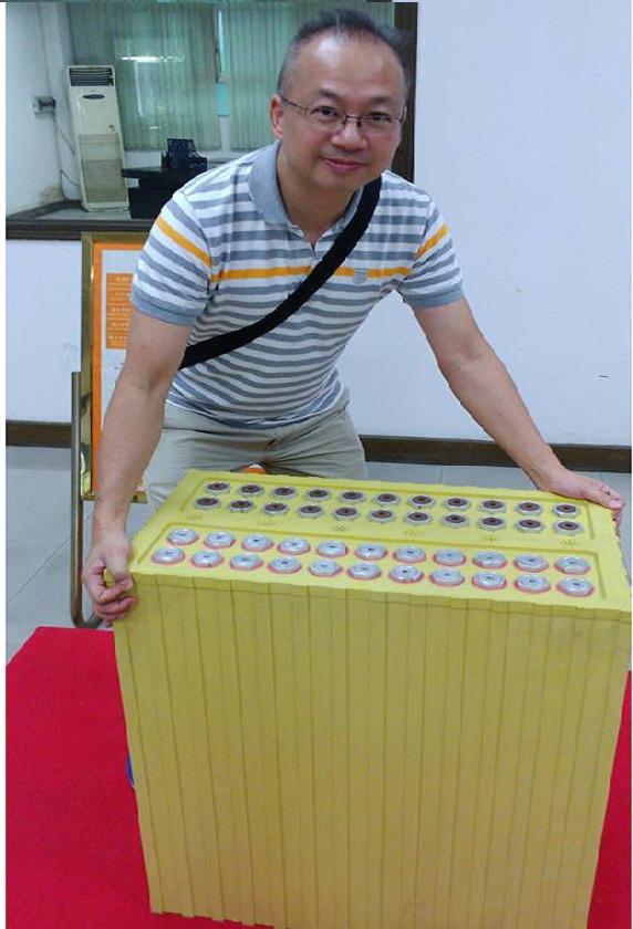
| United States Patent
|
6,686,096
|
| Chung |
February 3, 2004
|
Rechargeable solid state chromium-fluorine-lithium electric
battery
Abstract
There is disclosed a solid state rechargeable electric battery (10) including
a number of cathode plates (7) interposed among a number of anode plates (8) in
which the cathode plate (7) includes an aluminium foil (41) coated with a layer
of mixture (43) of lithium manganate, chromium and fluoride. The anode plate (8)
includes a copper foil (47) coated with a layer of mixture (49) containing
petroleum coke. Provided among the cathode plates (7) and anode plates (8) is a
solid state electrolyte (14) made up of lithium perchlorate dissolved in
ethylene carbonate and diethyl carbonate.
| Inventors: |
Chung; Hing Ka (Shenzhen, CN)
|
| Assignee: |
New Billion Investments Limited (HK)
|
| Appl. No.:
|
632907 |
| Filed: |
August 4, 2000 |
Foreign Application Priority Data
| |
Jan 27, 2000[CN] |
101356 A |
| Current U.S. Class: |
429/304; 29/623.1;
429/321; 429/322 |
| Intern'l Class:
|
H01M 006/18; H01M 006/00 |
| Field of Search:
|
429/304,306,307,322,324,321,326,325,330,331,332,333 252/62.2
|
References Cited
[Referenced By]
U.S. Patent Documents
|
5037712 |
Aug., 1991 |
Shackle et al. |
|
|
5296318 |
Mar., 1994 |
Gozdz et al. |
429/192. |
|
5478364 |
Dec., 1995 |
Mitate et al. |
|
|
5631104 |
May., 1997 |
Zhong et al. |
|
|
5712056 |
Jan., 1998 |
Matsumasa et al. |
|
|
5968683 |
Oct., 1999 |
Kolb. |
|
|
6001505 |
Dec., 1999 |
Fukuda et al. |
429/176. |
|
6156432 |
Dec., 2000 |
Mabuchi et al. |
428/408. |
|
2001/0046628 |
Nov., 2001 |
Oesten et al. |
|
| Foreign Patent Documents |
| A-20790/92 |
Feb., 1993 |
AU. |
|
| 0-413-313 |
Feb., 1991 |
EP. |
|
| 0-942-482 |
Sep., 1999 |
EP. |
|
| 942484 |
Sep., 1999 |
EP. |
|
| 56109461 |
Aug., 1981 |
JP. |
|
| 4-245170 |
Sep., 1992 |
JP. |
|
| 8-162114 |
Jun., 1996 |
JP. |
|
| 10-1 89045 |
Jul., 1998 |
JP. |
|
| 10-255794 |
Sep., 1998 |
JP. |
|
| 11-250914 |
Sep., 1999 |
JP. |
|
| WO 00/23380 |
Apr., 2000 |
WO. |
|
Other References
Australian Patent Office, Corrected International Search Report for
corresponding Hong Kong Short-Term patent application, Ref. No. CS/00/0048
(Sep. 18, 2000).
Letter by Kim Wellens (Australian Patent Office) re correction to first
reference cited on second page of Australian search Report of Sep. 18, 2000
(Dec. 19, 2000).
Australian Patent Office, International Search Report for corresponding Hong
Kong Short-Term patent application, Ref. No. CS/00/0048 (Sep. 18, 2000).
V. S. Bagotzky and A. M. Skundin, The Institute of Electrochemistry of the
USSR academy of Sciences "Chemical Power Sources", Academic Press, 1980, pp.
322-323 (No month available).
Derwent Abstract No. 87-26 4600/38, DD 245-531, Lithium-Manganese di: oxide
cell with specified tumescent layer compensating volumetric shrinkage and
maintaining good contact (Techn. Univ. Dresden) May 6, 1987.
David Linden, Handbook of Batteries, pp. 36.4-36.9 (McGraw-Hill, Inc.
2.sup.nd. ed., 1995) No month available).
Australian Patent Office, International Search Report for Hong Kong short
term patent application corresponding to 09/632,634; Ref. No. CS/00/0049
(Sep. 24, 2000). |
Primary Examiner: Ryan; Patrick
Assistant Examiner: Alejandro; Raymond
Attorney, Agent or Firm: Hall, Priddy, Myers & VandeSande
Claims
What is claimed is:
1. A solid state rechargeable electric battery including at least an anode
member and at least a cathode member, characterized in that a substantially
solid electrolyte is provided between said at least one anode member and said at
least one cathode member, wherein said electrolyte consists essentially of
lithium perchlorate dissolved in ethylene carbonate and diethyl carbonate.
2. A battery including at least an anode member and at least a cathode member,
characterized in that a substantially solid electrolyte is provided between said
at least one anode member and said at least one cathode member, wherein said
electrolyte is a dried product of a mixture comprising lithium perchlorate
dissolved in ethylene carbonate and diethyl carbonate in a liquid state wherein
said electrolyte comprises lithium perchlorate, ethylene carbonate and diethyl
carbonate in a relative liquid weight ratio of substantially 1:1:1.
3. A battery according to claim 2 wherein, prior to assembly of the battery,
said at least one anode member and said at least one cathode member,
respectively consist essentially of components other than said components of the
electrolyte.
4. A solid state rechargeable electric battery including at least an anode
member and at least a cathode member, characterized in that a substantially
solid electrolyte is provided between said at least one anode member and said at
least one cathode member, wherein said electrolyte comprises lithium perchlorate
and wherein said solid electrolyte comprises around 5-10% of the combined total
weight of said at least one anode member, said at least one cathode member and
said electrolyte.
5. A battery according to claim 4 wherein said electrolyte is a dried product of
a mixture of liquids comprising lithium perchorate dissolved in ethylene
carbonate and diethyl carbonate.
6. A battery according to claim 5 wherein lithium perchorate, ethylene carbonate
and diethyl carbonate have a relative liquid weight ratio of substantially
1:1:1.
7. A battery according to claim 4 wherein, prior to assembly of the battery,
said at least one anode member and said at least one cathode member,
respectively consist essentially of components other than said components of the
electrolyte.
8. A battery according to claim 5 wherein, prior to assembly of the battery,
said at least one anode member and said at least one cathode member,
respectively consist essentially of components other than said components of the
electrolyte.
9. A solid state rechargeable electric battery including at least an anode
member and at least a cathode member, characterized in that a substantially
solid electrolyte is provided between said at least one anode member and said at
least one cathode member, wherein said electrolyte is a dried product of a
mixture comprising lithium perchlorate dissolved in ethylene carbonate and
diethyl carbonate in a liquid state wherein the liquid weight content of the
lithium perchlorate in the electrolyte is substantially 1/3 of the total liquid
weight content of the electrolyte.
10. A battery according to claim 9 wherein the ethylene carbonate liquid weight
content of the electrolyte is up to 1/3 of the total liquid weight content of
the electrolyte.
11. A battery according to claim 9 wherein the diethyl carbonate liquid weight
content of the electrolyte is up to 1/3 of the total liquid weight content of
the electrolyte.
12. A method of forming a solid state rechargeable electric battery, including
the steps of:
(a) providing at least an anode member;
(b) providing at least a cathode member;
(c) providing an injectable electrolyte between said at least one anode member
and said at least one cathode member; and
(d) forming said electrolyte by dissolving lithium perchlorate in ethylene
carbonate and diethyl carbonate,
wherein said electrolyte is substantially solid when said battery is formed.
13. A method according to claim 12 wherein said lithium perchlorate, ethylene
carbonate and diethyl carbonate have a relative liquid weight ratio of
substantially 1:1:1.
14. A method according to claim 12 further including step (e) of injecting said
electrolyte between said at least one anode member and said at least one cathode
member.
15. A method according to claim 13 further including step (e) of injecting said
electrolyte between said at least one anode member and said at least one cathode
member.
16. A method according to claim 12 further including step (f) of drying said
electrolyte.
17. A method according to claim 13 further including step (f) of drying said
electrolyte.
18. A method according to claim 14 further including step (f) of drying said
electrolyte.
19. A method according to claim 15 further including step (f) of drying said
electrolyte.
Description
This invention mainly relates to a solid state chromium-fluorine-lithium ("CrFLi")
electric battery that can be discharged and recharged repeatedly, and to such an
electric battery which may be used for powering electric vehicles, e.g. electric
cars.
With a view to reducing pollution to the environment, various researches and
studies are being carried out around the world for the development of electric
batteries which may be used in place of petrochemical fuel for powering
vehicles, e.g. cars. Lead-acid electric cells, nickel-cadmium electric cells,
nickel-hydrogen electric cells and sodium-sulfur electric cells may at present
be used as electric accumulators for powering vehicles. It is generally believed
that lead-acid electric cells and nickel-cadmium electric cells may represent
the most commercially and technologically promising and viable candidates as
electric accumulators for electric power accumulators. Nonetheless, due to the
relatively low energy to weight ratio of these two kinds of electric cells, the
lengthy recharging time, and high requirements for maintenance, the development
of electric cars has been directly affected.
With the further research and development of power electric batteries, zinc-air
electric batteries, lithium ion electric batteries and proton-exchange membrane
fuel electric batteries have also been considered to be the best power electric
batteries for developing electric cars. However, the internal resistance of
zinc-air electric batteries is large, and the technology for the replenishment
of zinc ions has yet to be improved to be practical. As to lithium ion electric
batteries, due to the deposition of metal cobalt and lithium during repeated
charging, there is a risk of fire and explosion. As to proton-exchange membrane
fuel electric batteries, such have been thought by some to be the ideal power
source for powering electric cars. Nonetheless, there are yet a number of
difficulties to be overcome. Various practical and technical problems have also
been seriously hindering the development of the electric car industry.
An object of the present invention is to provide a rechargeable solid state
chromium-fluorine-lithium electric battery. A further object of the present
invention is to provide such a battery for use in powering electric vehicles,
e.g. electric cars.
According to a first aspect of the present invention, there is provided a solid
state rechargeable electric battery including at least an anode member and at
least a cathode member, characterized in that a substantially solid electrolyte
is provided between said at least one anode and said at least one cathode and
wherein said electrolyte comprises lithium perchlorate, ethylene carbonate and
diethyl carbonate. The battery does in one embodiment comprise an electrolyte
that essentially consist of the recited components. In another embodiment the
electrolyte is a dried product of a mixture of the aforementioned components in
a liquid state wherein said electrolyte comprises said components in a relative
liquid weight ratio of substantially 1:1:1. In yet another embodiment the
electrolyte comprises around 5-10% of the combined total weight of said at least
one anode member, said at least one cathode member and said electrolyte.
According to a second aspect of the present invention, there is provided a
method of forming a solid state rechargeable electric battery, including the
steps of (a) providing at least an anode member; (b) providing at least a
cathode member; and (c) providing an injectable electrolyte between said at
least one anode member and said at least one cathode member; characterized in
that said electrolyte is substantially solid when said battery is formed.
Embodiments of the present invention will now be described, by way of examples
only, and with reference to the accompanying drawings, in which:
FIG. 1 shows two solid state chromium-fluorine-lithium ("CrFLi") electric
batteries according to the present invention, in which one of said batteries is
partially cut out for illustration purposes;
FIG. 2 shows an enlarged view of the encircled portion marked "A" in FIG. 1;
FIG. 3 shows an electric battery assembly constructed of a number of
interconnected electric batteries shown in FIG. 1;
FIG. 4 shows a connection member for electrically connecting the electric
batteries shown in FIG. 1;
FIG. 5A shows an exploded perspective view of a gas release valve of the battery
shown in FIG. 1;
FIG. 5B shows a sectioned perspective view of the gas release valve shown in
FIG. 5A;
FIG. 6 shows an enlarged partial side view of a cathode plate of the electric
battery shown in FIG. 1; and
FIG. 7 shows an enlarged partial side view of an anode plate of the electric
battery shown in FIG. 1.
Two dischargeable and rechargeable solid state chromium-fluorine-lithium ("CrFLi")
electric batteries 10 are shown in FIG. 1. Each battery 10 includes a number of
cathode plates 7 interposed with a number of anode plates 8. While the cathode
plates 7 and anode plates 8 are here shown as planar, they may alternatively be
curved, in a rolled shape, or in other suitable configurations. The battery 10
includes a rigid outer housing 13, which may be made of polypropylene, or a
nickel-plated metal. Alternatively, the housing 13 may be made of a soft package
composed of polyurethane, aluminium foil and polyethylene.
On the top of the housing 13 are a cathode pole 3, an anode pole 4, and a gas
release valve 9. The cathode pole 3 is connected with the cathode plates 7 in
the housing 13, and the anode pole 4 is connected with the anode plates 8 in the
housing 13. Provided among the cathode plates 7 and anode plates 8 is a solid
state electrolyte, details of which will be discussed below. A safety cap 1 is
positioned above the cathode pole 3, and a safety cap 2 is positioned above the
anode pole 4. Both safety caps 1, 2 are made of polybenzothiazole. The safety
caps 1, 2 can avoid accidental short-circuiting among anode poles 4 and cathode
poles 3, when a number of batteries 10 are interconnected to form a battery
assembly so as to be able to provide more power.
On one major surface of the housing 13 is provided with a raised ridge 12 which
is inner of the bottom edge and side edges of this major surface. On another
major surface of the housing 13 is provided with a side ridge 11 which runs
along the bottom edge and two side edges of this major surface. The ridges 11
and 12 are so sized and configured that the ridge 12 of one battery 10 may be
force-fitted with the side ridge 11 of another battery 10 so as to engage and
secure the two batteries 10 together.
With regard to the lead-wires used in relation to this invention, pure aluminium
is best for making the cathode lug 5 and purple copper coated with nickel for
the anode lug 6 in the case of soft packing. In the case of a rigid housing,
stainless aluminium is best for making the cathode pole 3 and purple copper
coated with nickel for the anode pole 4.
A special thermal bonding method is best for the lead wires to be used in pole
lugs of this invention in the case of soft packing. In this way, permanent
sealing can be achieved. The rigid housing 13 should be sealed up and insulated
with chlorotrifluoroethylene.
In FIG. 3, four batteries 10A, 10B, 10C, and 10D are shown as being engaged and
secured with one another to form a battery assembly. The batteries 10A to 10D
may be electrically connected in a number of ways. One may connect the batteries
10A to 10D in series, e.g. connect the cathode pole 3 of the battery 10A with
the anode pole 4 of the battery 10B, and connect the cathode pole 3 of the
battery 10B with the anode pole 3 of the battery 10C, and so on. Assuming that
the output voltage of each of the four batteries 10A, 10B, 10C, 10D is the same,
the output voltage of the battery assembly as shown in FIG. 3 (when connected in
series) will then be four times the output voltage of each of the batteries 10A,
10B, 10C, and 10D. Alternatively, the batteries 10A, 10B, 10C, 10D may be
connected in parallel by electrically connecting all the cathode poles 3
together, and electrically connecting all anode poles 4 together. Again,
assuming that the output voltage of each of the four batteries 10A, 10B, 10C,
10D is the same, the output voltage of the battery assembly in FIG. 3 (when
connected in parallel) will then be the same as the output voltage of the
battery 10A, although the battery assembly can provide electricity at four times
the capacity of the battery 10A, and for a longer time.
FIG. 4 shows a connecting member 15 which may be used for electrically
connecting the electrode poles (i.e. the cathode poles 3 and the anode poles 4)
of the batteries 10. The connecting member 15 includes two rigid electrically
conducting end keys 17, each with a central hole 19. The end keys 17 are
connected by a bundle of electrically conducting wires 21. Both the end keys 17
and the wires 21 may, for example, be made of steel. As can be seen in FIG. 1,
each of the cathode pole 3 and the anode pole 4 is provided with an external
thread over which a nut 23 may be threadedly engaged. The end key 17 of the
connecting member 15 may thus be positioned over the cathode pole 3 or the anode
pole 4, and secured thereto by the respective nut 23. The electrode poles of the
various batteries 10 may thus be connected with one another as desired.
Turning to the gas release valve 9, such is shown in more detail in FIGS. 5A and
5B. As shown in these figures, the gas release valve 9 includes three
components, namely an upper body portion 25, an elastic ethylene propylene
terpolymer rubber piece 27, and a base plate 29. The base plate 29 includes a
central recess 31 provided with a gas release aperture 33, which is connected to
the interior of the electric battery 10. The rubber piece 27 is sized and shaped
to be receivable within the recess 31 of the base plate 29. The upper body
portion 25 includes a number of gas release holes 35 (of which two are shown in
FIG. 5A) on a side wall 37 of a raised tubular portion 39. When assembled, the
rubber piece 27 sits in the recessed 31 and closes the gas release aperture 33,
and the upper body portion 25 is fixedly secured (e.g. by laser welding) to the
base plate 29.
During the manufacture of the battery 10, gas of the solvent (e.g. ethylene
carbonate, diethyl carbonate) of the electrolyte may be generated, which has to
be released from the battery 10, so as to avoid explosion. When the internal gas
pressure in the battery 10 exceeds a predetermined level (e.g. the atmospheric
pressure), the gas from the gas release aperture 33 will exert an upward
pressure on the bottom of the rubber piece 27, to cause the latter to bulge up,
so that gas from the interior of the housing 13 of the battery 10 can enter the
cavity of the raised tubular portion 39 of the upper body portion 25 via the gap
left between the circular edge of the rubber piece 27 and the base plate 29, and
thence to the outside environment via the gas release holes 35. While the
generation of gas usually only occurs during the first formation/production of
the battery 10, for safety sake, this gas release valve 9 is retained in the
battery 10, so as to ensure that in case the internal pressure of the battery 10
exceeds the predetermined level during recharging and or discharging of the
battery 10, the gas inside the battery 10 will be released, and that the gas
release aperture 33 (and thus the valve 9) will be properly closed when the
internal pressure of the battery 10 is lower than the predetermined level.
The gas release valve of conventional lithium ion electric batteries and
alkaline batteries (e.g. those used in portable computers) mainly makes use of
the rupture membrane structure, in which when the internal pressure of the
battery exceeds the predetermined level, the membrane will rupture (i.e. break)
to allow gas to be released from the interior of the battery to the outside
environment. However, with the rupture of the membrane, the battery can no
longer be used. For specially designed high power electric batteries, the gas
release valve is mainly of the spring-ball closure structure in which a closure
ball is biased by a spring towards a position to close the valve. However, when
the internal gas pressure of the battery exceeds the designed level, the closure
ball will be moved by the gas in the battery, against the biasing force of the
spring, and away from the closed position so as to release the gas in the
battery to the outside environment.
The structure of the conventional gas release valves discussed in the preceding
paragraph is rather complicated and requires precise machining. In addition, the
rupture membrane structure is not suitable for large-current repeatedly
rechargeable and dischargeable electric batteries. As to the spring-ball closure
valve, deformation, e.g. of the spring, may occur as a result of being under
pressure for a long period of time. In addition, the production cost of such a
valve is high.
On the other hand, the ethylene propylene terpolymer rubber piece 27 used in the
present invention possesses the following advantages:
a. it is resistant to acids, alkalis and organic chemicals;
b. there exists a linear relationship between the pressure and the extent of
deformation;
c. there is no change to the elasticity upon prolonged and repeated use;
d. relatively low price;
e. easy to manufacture, and does not require precise machining; and
f. good closure effect.
A gas release valve with a closure membrane made of ethylene propylene
terpolymer rubber is thus best suited for use in repeatedly dischargeable and
rechargeable electric batteries, as in the present invention.
FIG. 6 shows an enlarged partial side view of a cathode plate 7 of the present
invention. The cathode plate 7 includes an aluminium foil 41 of a thickness of
0.3 mm. On both major surfaces the aluminium foil 41 is coated with a layer 43
made of the following ingredients:
83-90.5 wt % of lithium manganate (in spinel type structure, which may be
obtained from UMEX Inc., of Belgium);
1-2 wt % of chromium;
1.5-3 wt % of lithium fluoride;
5-8 wt % of acetylene black; and
2-4 wt % of graphite.
The above ingredients are then mixed and dissolved in water and/or ethanol, and
subsequently coated onto the aluminium foil 41. The layer 43 will solidify when
the coated aluminium foil 41 is heated up to around 300.degree. C. The thickness
of the layer 43 is around 0.25 mm. On top of each of the layers 43 is a further
dividing layer 45 made of a tribasic acrylic acid. Each of these dividing layers
45 is of a thickness of about 0.1 mm. When the aluminium foil 41 is again heated
up to dry/solidify the dividing layers 45, a unitary cathode plate 7 will form.
It is found in practice that the aluminium foil 41 has to be thicker than each
of the coating layers 43. It is also found in practice that the existence of
chromium allows the battery 10 to be recharged or to discharge at a rate of over
1C of its designed capacity. The meaning of the symbol "C" will be discussed
herebelow. As to fluoride, it is found that such allows the battery 10 to
discharge at a high temperature of over 50.degree. C.
As to the anode plate 8 shown in FIG. 7, such includes a copper foil 47 of a
thickness of around 0.35 mm. On both major surfaces of the copper foil 47 is
coated with a layer 49 of a thickness of around 0.36 mm. The layer 49 is made of
a mixture of:
petroleum coke ground to a particulate size of 30-40 .mu.m;
1-2 wt % of graphite; and
0.5-1 wt % of acetylene black.
These ingredients are mixed and dissolved in water and/or ethanol as solvent,
and subsequently applied onto the copper foil 47. The copper foil 47 is then
dried by heating, whereby a unitary anode plate 8 is formed. It is found in
practice that each of the layers 49 has to be thicker than the copper foil 47.
When the cathode plates 7 and the anode plates 8 are interposed with one another
as discussed above, a dissolved electrolyte is then injected into the space
among the cathode plates 7 and anode plates 8. The electrolyte is substantially
made up of 1/3 in weight of liquid lithium perchlorate (LiClO.sub.4), 1/3 in
weight of liquid ethylene carbonate (HOCOOCH.dbd.CH.sub.2) and 1/3 in weight of
liquid diethyl carbonate (CH.sub.3 CH.sub.2 OCOOCH.sub.2 CH.sub.3). The
electrolyte (together with the ethylene carbonate and the diethyl carbonate) is
around 5-10% of the weight of the battery 10 (minus the outer casing). When the
electrolyte is dried up, such will be in a solid form and substantially free of
any liquid, as shown by numeral 14 in FIGS. 1 and 2.
In order to maximize the usable life and capacity of the electric battery made
in accordance with the present invention, it is found in practice that when the
battery is first manufactured, such should be charged for the first time at a
substantially constant temperature above 48.degree. C. (with a variation of no
more than .+-.0.1% of the mean temperature), and at a rate of 0.1C to 0.2C of
the designed capacity of the single battery 10. The meaning of the symbol "C" as
used in the field of the manufacture and design of electric batteries may be
understood from the following table:
TABLE 1
Battery Charging/ Charging/
Capacity Discharging Rate Discharging Current
100 Ah 1 C 100 A
(Ampere-hour) 2 C 200 A
5 C 500 A
0.1 C 10 A
0.2 C 20 A
200 Ah 1 C 200 A
2 C 400 A
5 C 1,000 A
0.1 C 20 A
0.2 C 40 A
An electric battery manufactured as discussed above may be directly used in an
electric car as a source of electric power. After the first formation of the
battery, it may be rapidly recharged at more than 3C of the designed capacity of
the battery 10.
The use of lithium perchlorate as the electrolyte in the solid state conducting
base not only significantly lowers the production cost, but also increases the
usable life of the battery and increases its stability in high temperature. It
is found in practice that such a battery is safe even if dissembled and exposed
to the environment, as it is non-toxic. It may be repeatedly recharged and
discharged for over 2,000 times, and the capacity can still remain at least 75%.
The storing temperature of a battery according to the present invention can be
from -40.degree. C. to 70.degree. C., and its working temperature can be from
-20.degree. C. to 60.degree. C. It is usually discharged at a rate of 2C of the
designed capacity of the single battery 10, but may also be discharged at pulse
at a rate of up to 5C of the designed capacity of the single battery 10, if
necessary.
It is found in practice that a solid state electric battery constructed in
accordance with the present invention is both simple and compact, non-toxic,
high in power, can withstand discharge and recharge at a large current rate, can
be recharged at a relatively short time, is of a long usable life, and can be
recharged and discharged repeatedly.
As the crystal structure of LiMn.sub.2 O.sub.4 is very stable after being mixed
with other ingredients, e.g. chromium and fluorine, there will be no change to
the crystal structure even at a high temperature and upon repeated charging and
discharging. It is thus safe even to charge each battery 10 up to 5V, its
production cost is roughly one half of that of LiCoO.sub.2 battery. The use of
ground petroleum coke as a raw material in the manufacture of the anode also
significantly reduces the production cost of the present battery.
The CrFLi solid power battery according to this invention may not only be
applied to electrically-powered vehicles and other kinds of battery-driven
transportation locomotives, but also be grouped into battery containers of
different power by series connection or parallel connection to meet other power
requirements, such as standby power supply for communications apparatus, power
stations and control facilities, power supply for electrical appliances, and to
provide lighting in remote villages, out posts and field work areas, and to
serve as future domestic power reserve.
The repeatedly rechargeable and dischargeable CrFLi battery according to this
invention can be manufactured into batteries for portable phones, small-sized
batteries for electronic diaries, computers, video cameras, cameras etc, and
batteries for domestic standby power supply of high power.
* * * * *
| |

|